 Law Enforcement Software
Law Enforcement Software
The status monitor map page shows a snapshot of the CAD status monitor as of a specific time in a special (map) format. The data represented on this map will be identical to the data represented on the status monitor page providing that all units and events have latitude and longitude information associated with them. Any status monitor unit/event hiding or filtering that has been activated will be honored on the map page as well as on the primary status monitor display. As GPS equipped field unit move around they report their respective location to the MD Controller. The MD Controller rebroadcasts this information to the other field units to create a visual representation of the locations for all field unit.
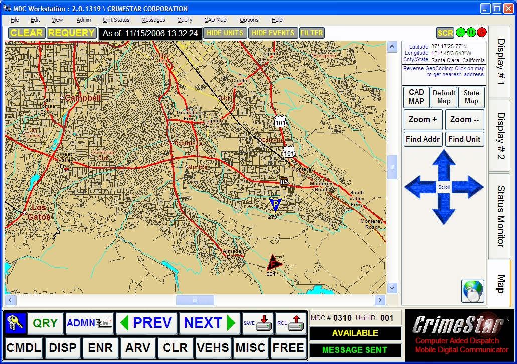
Units and Events are depicted on the map using icons to represent the event or unit type being referenced. These icons will change or move on the map as new status information is received from the MDC controller.
Map Icon Click - Information: By clicking on either Unit Icons or Event Icons that are displayed on the map, the MDC software will display the related status monitor data associated with that specific map icon.
Latitude & Longitude Reference: As you view the MDC map page you will notice that in the upper right corner of the page the system will show you the latitude, longitude, county and state reference. This information is automatically updated as you move the mouse cursor/pointer over different parts of the map. Latitude and Longitude values can be defined in Degrees or as a Decimal value. By default latitude and longitude coordinates are represented as degrees. To change them to a decimal value select “Show Latitude & Longitude as Decimal” from the Options menu.
Reverse Geo-code Reference: When you click on the MDC map page the system will attempt to mathematically calculate the nearest physical address to that specific map point.
Map Views: Similar to the map page used in CAD, the MDC status monitor map page has 3 different map displays that can be selected. The map files installed on the MDC workstation and your specific environment will determine which displays you use and when.
• The CAD Activity Map is a calculated map and will display a region that encompasses all defined units and events.
• The “Default Map” displays a map based upon a default view that you define. Using the zoom and scroll keys to position the map to the desired display, the user can right-click the Default Map button to SET the default map display. Once set the user can return to that map view at any time by clicking the Default Map button.
• The “State Map” display will show a high level view of the state.
Zoom+ / Zoom - : These buttons will zoom in or out on the current map page without changing the center point reference of the map.
Find Address: This button will activate a find address dialog box prompting the user to enter an address delimited by commas. Once entered the software will attempt to find or locate that address on the map and will center the map page on the point that calculates to that address.
Find Unit: This button will prompt the user to identify a unit to locate on the map. One the user identifies the unit to find the MDC software will locate the unit on the map page and center the map on that unit.
Navigation Arrows: The blue directional navigation arrows can be used to reposition the map by moving the center point of the map up, down, right or left.
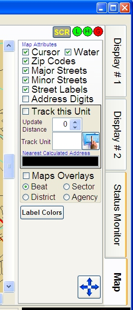
Map Configuration Panel: Clicking the map configuration page toggle button (as shown) will switch the map navigation panel to a map configuration panel. This will allow the user to set certain map attributes and activate certain map functions to be activated. When this toggle button is clicked the graphic on the button will change to the blue navigation arrows, so the same toggle button can be user to toggle back to the map navigation panel.
|
On the map configuration panel various map attributes can be turned on or off. This will affect how the map is displayed and how much detail it will provide. Generally the default setting for these map attributes provide the best map usability. Also on this page is the ability to track units.
The “Track this Unit” option can only be used when a GPS receiver has been installed and is activated. This option will cause the MDC software to always keep the map centered on this MDC unit (“this unit”). The optional update distance parameter can be used to determine the amount of movement needed before the map is updated. Keeping this setting at zero (0) will cause the map to be updated in real time. The “Track Unit” field allows you to define a unit to track and center the map around. This is accomplished using the LAT/LNG data of the other units as supplied by status monitor broadcasts or by a manual REQUERY of the unit status data. This update will not be real-time and will be delayed by the frequency of status monitor updates but will keep the map focused and centered on a specific unit.
* The “Track this Unit” setting will always override the general “Track Unit” setting. When tracking units the system will always attempt to calculate the nearest address and display that address for your reference. |
|
Map View Overlays: By clicking the “Map Overlays” option turn this feature on while selecting either “Beat”, “Sector”, “District” or “Agency” will determine which series of map overlays are to be displayed. (See “Creating a Status Monitor Map Overlay Files” for more information on map overlays)
• Map Files Installed / Configuration (See Installation Notes)
Map Unit Icons: The graphic of the map shown above illustrates the use of static image icons showing a police car, fire truck, ambulance etc. While these icons do represent the unit type they cannot represent the unit’s direction of travel as reported by the GPS system. Alternately, unit icons (bitmap graphics) representing police, fire, ambulance/medical and other units will be displayed using color coded triangular graphic icons. Whenever possible the triangular icon will be oriented in the compass heading/ course direction (N, NE, E, SE, S, SW, W, and NW) of the unit as reported by the GPS signals from that unit.
|
Police Unit Icons: |
|
|
Fire Unit Icons: |
|
|
Medical Unit Icons: |
|
|
Other Unit Icons: |
|
|
This Unit Icon: |
|
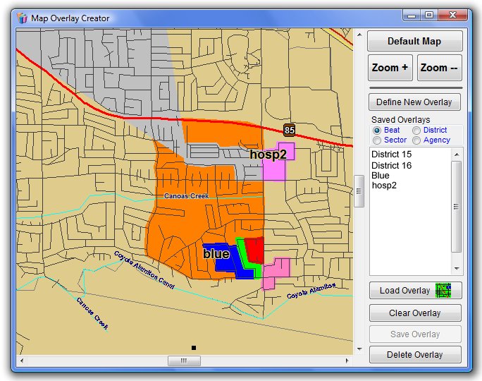
• Creating a Status Monitor Map Overlay File
The Crimestar MDC software distributes with a companion program called mapoverlays.exe that can be used to create map overlays file (mapareas.xml) depicting various beat, sector district or agency boundaries as graphical semi-transparent color map overlays.
Once the map overlay file (mapareas.xml) is created it must be manually distributed to each MDC workstation before the overlays will be viewable.